
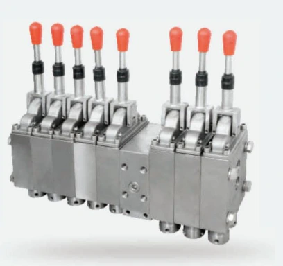
Printed specifications.
English reference transcription from original PDF page 19, printed page 5. Visually transcribed from the supplied catalogue; not an independently verified operating specification.
| Nominal pressure (paired listing) | 31.5MPa |
|---|---|
| Nominal flow (paired listing; confirm unit) | 400L/mm in the paired configuration listing |
| Material descriptions (as printed) | English text: Stainless steel; Chinese text: stainless steel or 45# |
| Nominal medium (as printed) | 5% emulsified oil & 95% neutral water emulsion (English text as printed) |
Confirm before ordering.
- Confirm the intended flow unit: the catalogue prints L/mm. It has not been silently converted to L/min.
- Confirm the material grade and ordered configuration: the English and Chinese material descriptions are not identical.
- Original drawing excerpts are provided where available without multilingual specification blocks; confirm the exact interface and drawing revision before ordering.
- This model is named in a paired FHS400/FHS320 configuration heading. The panel specifies the combined listing, not a separately confirmed rating for every individual model. Confirm the assembly and control configuration.
- The paired configuration is repeated on printed pages 5 and 6; the original bilingual source remains available in the catalogue download.
Dimensions & circuit symbols.
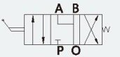
Source dimension labels
| Left outer vertical | 118 |
|---|---|
| Left inner vertical | 96 |
| Central horizontal dimensions | 32; 35 |
| Lower horizontal dimension chain | 80; 20 |
| Overall lower horizontal | 114 |
| Hole callout | 4-Φ13 |
| Drawing and schematic port labels | A; B; P; O |
Transcribed from the drawing labeled FHS320/31.5 in the upper paired FHS400/31.5(3) / FHS320/31.5(5+1) panel, original PDF page 19, printed page 5. No dimensional unit or thread designation is printed in this drawing; no unit is inferred here. O is preserved as printed. Confirm the complete approved drawing and configuration before selection.
- Original dimension drawing and hydraulic schematic, where shown. All geometry, dimension figures and port labels are reproduced unchanged from the catalogue.
- Interface configuration can be customized according to user requirements (translation of the catalogue note); confirm the exact ordered interface and current drawing revision.
- The original product photograph shows a paired FHS400/FHS320 assembly, not an individually isolated valve. Confirm the required assembly and control configuration.
- Self-locking operating mechanism (translation of the Chinese assembly description).
The adjacent bilingual heading overlaps the rectangular boundary needed to retain the complete dimension labels. To avoid clipped dimensions or altered engineering artwork, the dimension drawing remains available in the original catalogue download rather than the primary English-only image gallery. The separate hydraulic schematic is retained.
These are direct excerpts, not redrawn engineering figures. Do not scale an on-screen image to determine manufacturing dimensions. Request the approved dimensioned drawing and confirm its units and revision. The catalogue with English certificates and original bilingual product pages is available separately for source verification.
Certificate cross-reference.
No exact model-label match was found among the 25 certificate scans supplied in this catalogue. This does not establish that the product is uncertified. Request the current document for the exact model; do not substitute a certificate for a similar-looking valve.
Browse the supplied certificate library